Long exposure photography with Arduino and LEDs
This is a write up of how I built my light painter, going through the software, the materials, the design of the custom parts and putting everything together. Below are links to all the different sections, so you can skip to the bits you’re really interested in or you can continue for a more or less linear process.
- Introduction and goals
- Hardware
- Arduino sketch
- Enclosure and assembly
- Conclusions
- Links and references
1. Introduction
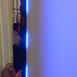
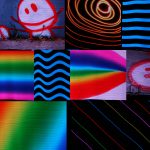
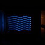
The main concept behind light painting (wikipedia article for more detailed info) is using a light source that is moved in front of a camera during a long exposure shot. The light source can be as simple as a hand held torch or a LED, but with a microcontroller, a LED strip and precise timing, we can create complex images and scenes.
Besides a LED strip and a micro controller, we need a portable power source and an easy way to load images. We will have to program our microcontroller to load an image, convert it into information that we can send to our LED strip and then drive the succession of lines to create a full image.
This has been done before, many, many times; and even commercially. But I wanted to build my own, both to learn in the process and because commercial options were out of my budget. I chose adafruit’s implementation as a starting point, because it worked on the hardware I already had and they have provided detailed instructions. I also wanted some additional features: I wanted to add a display and a menu system to be able to choose the image to display and adjust the settings (like brightness or speed). I also wanted to be able to turn off the brightness balancing that adafruit’s sketch did, because frame or animation painting wasn’t something I really needed. And most importantly, I adjusted the project to the materials I had at hand.
2. Hardware
This is an outline of the materials I used (note: the following are affiliate links; they would help me out at no cost to you, but I understand if you’re not into the idea):
- Arduino UNO.
- LED strip, any flavor of RGB addressable will work; I used a WS2812 strip like this one.
- 8 AA batteries. I use eneloop rechargeable ones.
- 8xAA battery holder.
- Alternatively, you could use a LiPo battery, but then you would need protection and charge circuitry.
- UBEC or buck converter to get a stable 5V from our power source
- Micro SD card reader module. I used these.
- 1602 LCD + I2c LCD module, like this one.
- 24awg cable for Arduino and logic conecctions
- 20awg cable for UBEC to LED strip
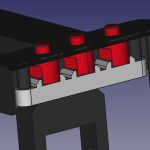
- Momentary push buttons
- Slide switch
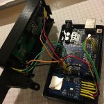
This is a pretty simple schematic of how everything goes together.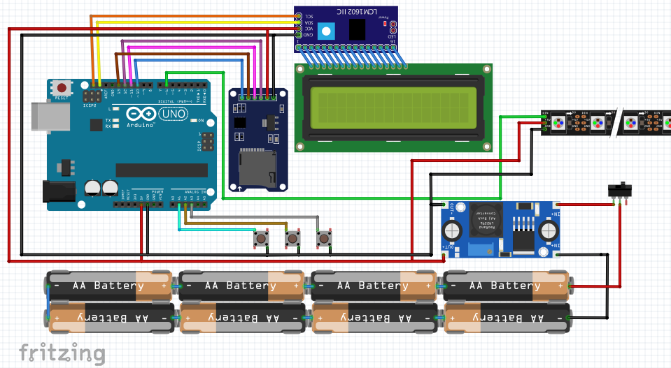
The battery pack feeds into the UBEC with a switch that’s our master power on/off. The UBEC feeds 5V to the LED strip, the Arduino and all the other components. The mini-SD reader connects to pins 10 through 13, and the LCD-I2C adapter connects to SDA and SCL. Apart from that, the buttons are wired to A1, A2 and A3, and the digital in for the LED strip is connected to pin 6.
3. Arduino sketch
This sketch is based on the the one written by Phil Burgess/Paint Your Dragon for Adafruit, that can be found here. A complete write-up with instructions and hardware design can be found on Adafruit’s website (where there’s also more in-depth info on some of the components and design choices).
What I did is add an LCD to the sketch, compartmentalize the functions so that the loop was mostly waiting and acting upon user input and implement a (probably quite crude) menu system. The output and menu system was constrained by the limitations of a 16×2 display, which was also fun to get around.
I wanted the sketch to be able to present a menu with the available files in the SD, but reading all the files and populating an array with the names would’ve meant using a prohibitive amount of memory. The workaround is to scan the files that we’re interested in and store their file index (a much smaller memory footprint). Then we pull up the names on the fly. But even with this we are limited to 30ish files.
The images we use are 24 bit bitmaps, because their file format is pretty straightforward to decode, unlike more CPU intensive formats like png or jpeg (we’re talking at the 8-bit microcontroller level here).
The Arduino isn’t powerful enough to decode the files on the go, so on init or brightness recalculation, the files are scanned and converted to a raw format that later can be dumped directly to the lcd strip without any conversion. All the file loading, conversion and dumping was already taken care of in Phil’s sketch, so all credit to him.
Memory was the main limitation throughout, and I constantly kept getting stack collisions while I was developing the sketch. I peeled away variables and code (like the whole Serial interface) until I got it to run smoothly. I’m not great at C, so I’m sure that there are multiple optimizations that could give a bit more breathing room or things that could be more efficient in their use of variables (and memory). If you spot something I’d love to hear your thoughts.
The menu is quite simple. 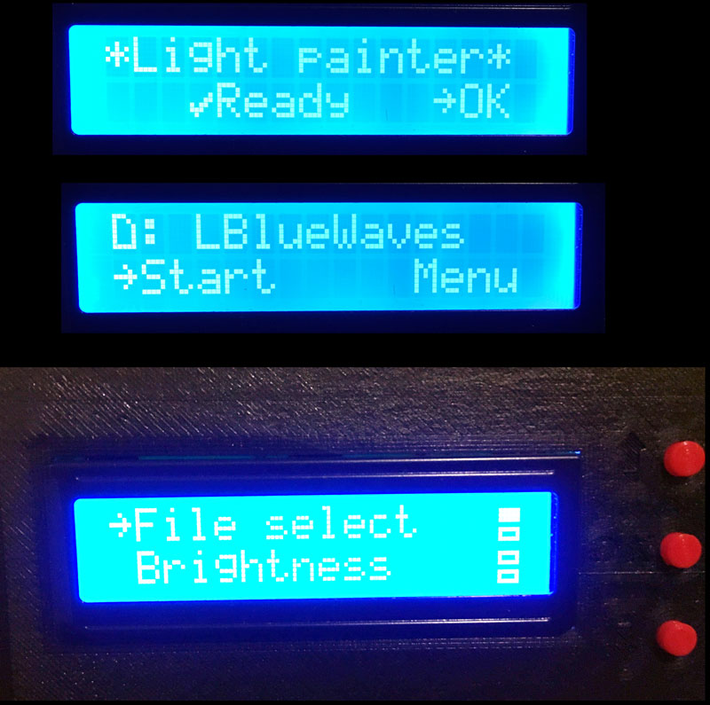 We can select the image we want to trigger, the brightness (which triggers a file rescan), the speed at which the image is displayed and the delay before the display starts.
Additionally, we have the option to save the settings to EEPROM, so that our current settings are restored the next time we power on.
I’ve also changed some routines to make boot quicker by prompting the user if a complete rescan should take place and rationalizing the generation of the raw files. Though Phil had ingeniously managed to get 3 different settings with just a potentiometer and push button, all that is now handled by the menu.
Please check out the code on Github (Light-painter), and feel free to let me know if there’s anything that can be improved.
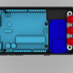
4. Enclosure and assembly
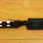
This is the part that will depend the most on the materials you have easier access to or the ones you feel more comfortable working with. I tried to keep things simple, so I used a beam of wood to support the LED strip and I decided to design a custom enclosure that I would 3D print.
I used FreeCAD for the design. There was some amount of swearing and starting over, but in the end I managed to get something pretty close to what I had imagined.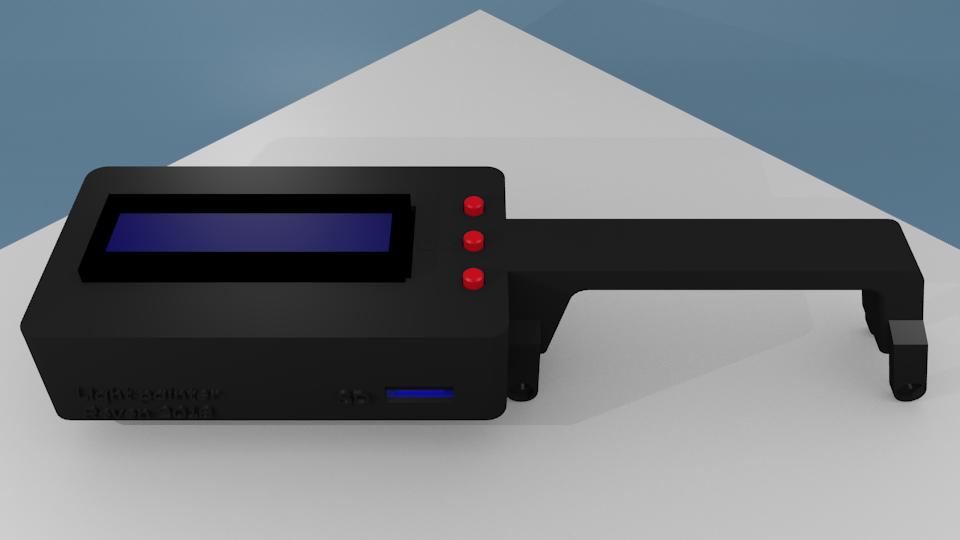
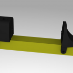
I made custom adapters for the battery holder as well, that leave spaces for cable routing. Admittedly, this could’ve been done differently, but this was the simplest option
You can download the STL files from Thingiverse: Light painter. However, after using the light painter, I have found a few issues with my designs. I might tackle these in future revisions:
- The screw tabs are not strong enough. They would need a thicker material or to be printed on the XY plane to have more tensile strength.
- The pins that hold the Arduino and the SD module in place are way too thin and long to be practical. They break. Easily. This could be fixed with thicker pins that narrow out at the point of contact.
- There is barely enough space inside the enclosure for all the cables. Make sure your cables are flexible. If I had to design the box again, I’d make it more roomy and leave enough space for the UBEC.
- I would add some kind of tab or latch to keep the bottom and top halves together. The two point fixture of the top half to the beam is not enough to close down (specially due to the previous point).
- The button system I designed is horrible. It’s impossible to keep it in place. Once installed it works, but this would be something to definitely improve.
That said, everything fits in snugly and closes down with a few coercive drops of superglue. The main enclosure goes onto the beam, as well as the battery pack. Everything is connected as in the schematic.
The UBEC lives on the outside. Not as elegant, but it probably gets much more adequate cooling there and it’s not like it takes up a lot of space.
The placing of the battery pack and the main enclosure could be optimized. I just placed it based on the beam where it looked right and made sense from a cable routing point of view, but I didn’t actually test to get the best balance. The light painter feels ok to handle; a bit top heavy but not unwieldy.
5. Conclusions
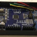
Overall this was a fun project. Most of the effort went into writing and testing the script while most of the components were plugged into a breadboard. Designing the enclosure and battery holder blocks was probably a bit overkill, specially since they were my first time ever in FreeCAD, which sometimes just doesn’t like your geometry but it doesn’t tell you why, so you have to keep iterating different ways to create the same geometries until it suddenly works.
But it was great to design from the ground up, integrating software and hardware until reaching a functional device.
I’d love to hear your thoughts: drop a comment if you have any questions or if you would’ve done something differently and why.
6. Links
- Light painter sketch on Github: https://github.com/reven/Light-painter
- STL files on Thingiverse: https://www.thingiverse.com/thing:2849881
- Adafruit’s tutorial: https://learn.adafruit.com/neopixel-painter
- Adafruit’s sketch on Github: https://github.com/adafruit/NeoPixel_Painter
Hi, great work!!!!! Is it possible use Arduino nano?? Thank you for your work
Hi Leonardo, thanks.
Yes, it should be possible to use an Arduino nano, but you have to be careful that you have a ATmega328P based nano, the one with 1kb EEPROM, 2kB SRAM and 32kB Flash. The sketch won’t fit (or run) on the ATmega168 based nanos.
Apart from that, SDA and SCL go to pins A4 and A5 if I remember correctly. Send me a picture if you build it!
hi, thank you for answer. When i do it i make many photo and i send you.
I have a problem whit file, i had make bmp at 24bit image but when i load by arduino it tell me :
🙁 error
creating file
and
raw file error
re-scan needed!
I do ti but nothing change
Why?
Thank you
Try to download the sketch again. I made a few changes a few days ago and it shouldn’t produce this error now. The other thing that can cause it to fail is if there are already other files on the SD card or if there are too many files. Let me know if it works.
YEAHHHHH!!!!! I’ ve resolved, i must powered my sd reader by 3,3 Vcc and not by 5Vcc!!!!
See you soon
Hallo,
Super Arbeit.
Kannst du mir bitte dein FreeCAD Project zusenden/veröffentlichen um deine Anmerkungen umzusetzen?
Hello,
Good job.
Can you please send me / publish your FreeCAD Project to implement your comments?
Hi Gerd. Danke. 🙂
To be completely honest, the only reason I haven’t published the FreeCAD files is because they are my first attempt at designing something in FreeCAD and they are quite ugly and full of errors. I had to hack the STLs together, so I’m not very proud of them and wouldn’t want anyone to distribute them.
I successfully build it, but suddenly it’s just showed “. . .”, already upload the program and formatted the SD card with no success. Please help.
Hi Eyang,
Please try downloading the code again, I did make some changes after publishing the post and there were some errors that I didn’t notice. Also make sure that your ubec/buck converter can handle the amperage of the LEDs, or it will brown out the Arduino and it’ll hang, which might be what you are describing.
Hello, first of all thank you for sharing the light painter project.
And I was able to upload the code without problems to the arduino with version 1.1, the menu on the screen works correctly, the card reads it to me the image that is perfectly good but the bad thing is when it is reproduced in the led strip that remains in black the screen and the LEDs do not light up.
Have I read that you have a new version?
Please help
Thank you
Hi Jose,
These would be the things I would start troubleshooting:
hi, great project. I would like to incorporate a “128×64 OLED display” instead of the “1602 LCD”. How should I modify the code, can you help me?
Hello, I am following the steps to be able to build the project, but when trying to verify I get these errors:
-exit status 1
within this context
if(outFile.createContiguous(sd.vwd(), outName, 512L * bmpHeight)) {
-exit status 1
‘show’ was not declared in this scope
show(); // Display current line
Can you help me on what might be going on. Thank you